* 본 게시물은 '19. 7. 29(월)에 추가로 수정되었습니다.
Tizen IoT Preview는 Tizen 4.0에서 베타 버전으로 한시적으로 지원되었습니다.
Tizen 5.0에서는 더 이상 사용할 수 없습니다.
출처 : https://developer.tizen.org/development/iot-preview/iot-apis
IoT APIs
The Tizen IoT API provides a common set of interfaces allowing you to build compelling IoT device applications which achieve native performance. The characteristics include:
- Common set API, which means that the Tizen IoT API is based on the Tizen 4.0 common profile. The API supports the common set of mobile, wearable, and TV profiles and allows you to make IoT applications, such as network audio applications.
- Available platform binaries, which allow you to efficiently create an IoT application. Tizen Common Headed binaries for Raspberry Pi 3 and ARTIK 530 have passed the API test verification, which means that you can create IoT applications with a productive quality.
In Preview 1, the Tizen IoT API releases only the native "C" API. Other convenient language types for the API are to be considered in the future.
The following table lists the IoT-specific Tizen platform API group.
Things SDK API
Developing "Things" which are market-ready (with cloud support) has been a challenge for most of the companies and individual developers. The SmartThings™ Things SDK API helps you to create new IoT devices easily. The version number of the first release is 0.9, which is the preview version.
The 2 core components for creating a new device are:
- SmartThings™ Things JSON Configuration file (
device_definition.json)For more information on the configuration file details, see Device Definition.
- Application logic and user interaction
For more information on using the SmartThings™ Things SDK API, see API Usage.
Figure: Creating a new device
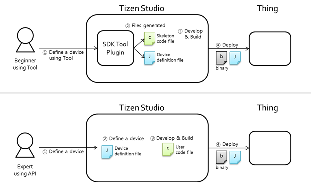
The SmartThings™ (ST) Things SDK provides you an easy and configurable option to build and deploy your own devices quickly:
- The ST Things SDK provides JSON-based things definition, which:
- Defines device and platform information.
- Defines resources that the thing is supporting.
- Defines an easy-setup configuration.
- The ST Things SDK provides spec-agnostic APIs, which:
- Hide the interface and resource type details in a request data.
- Divide a collection resource request into single resource requests.
- Provide the "property_key" in case of the GET request.
The SmartThings™ Things SDK API provides the following benefits for you:
- Supporting pin-based and UserConfirm(Certificate)-based OTM in EasySetup.
- Providing a JSON-based device/resource definition method in a single file:
- Includes Single resource and Collection resource support.
- Resources that are defined in a JSON file/string are made internally.
- Easy APIs to handle requests and responses:
- Supports request methods: GET and POST.
- You only need to make a representation (bundle of property values) for a response.
- You do not need to handle interfaces, as they are handled internally.
- The request to a collection resource is divided into individual requests to single resources.
- Cloud setup (Sign-up/Sign-in/Sign-out/Resource publish to cloud) is handled internally.
- Following operations are handled internally:
- To respond to an Access Point List (APList) request from a client.
- To start and stop softAP.
- To connect to a target WiFi AP (Enroller).
- To make the whole response data according to the interfaces (such as
oic.if.baseline,oic.if.b, andoic.if.ll).
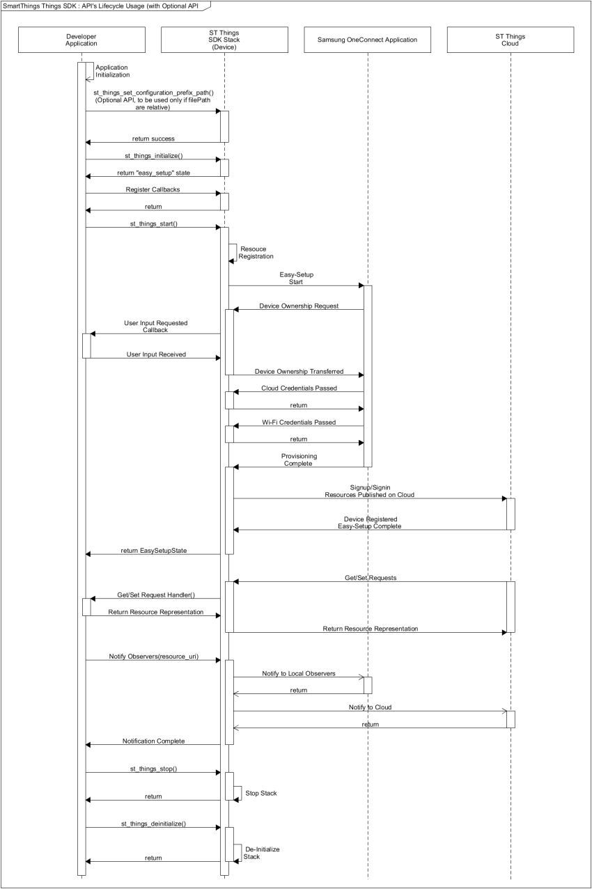
API Usage
The following figure illustrates the SmartThings™ Things API life-cycle.
Figure: SmartThings™ Things API life-cycle
Initializing Stack and Callbacks
Once the device configuration JSON file is ready, you can specify the read-only and read-write paths in the st_things_set_configuration_prefix_path() function (optional), and specify the file in the st_things_initialize() function:
bool easysetup_complete = false;
st_things_set_configuration_prefix_path("/ropath/XXX/res", "/rwpath/XXX/data"); /* Optional */
st_things_initialize("sample_device.json", &easysetup_complete);

/* User input can be handled graphically or using CLI */
/* You need to decide that */
if (!easysetup_complete) {
    int cmd = 0;
    printf("[%s]Start Easysetup ? (1:yes, other:no): ", TAG);
    scanf("%d", &cmd);
    if (1 != cmd) {
        st_things_deinitialize();

        return 0;
    }
}

/* Register Callbacks */
st_things_register_request_cb(handle_get_request, handle_set_request);
st_things_register_reset_cb(handle_reset_request, handle_reset_result);
st_things_register_user_confirm_cb(handle_ownership_transfer_request);
st_things_register_things_status_change_cb(handle_things_status_change);

st_things_start();
printf("ST Things Stack started\n");

handle_main_loop();

st_things_stop();
printf("ST Things Stack Stopped\n");
st_things_deinitialize();
printf("ST Things Stack deinitialized\n");
You must define the highlighted code in the above example. The st_XXX() functions come from the ST Things SDK API. For more information, see the API Documentation.
Getting and Setting Request Handling Callbacks
Assume that the following resources and resource types are defined in the sample_device.json file:
Example: Resources and resource types
"resources": { "single": [ { "uri": "/switch", "types": [ "oic.r.switch.binary" ], "interfaces": [ "oic.if.a", "oic.if.baseline" ], "policy": 3 }, { "uri": "/audio", "types": [ "oic.r.audio" ], "interfaces": [ "oic.if.a", "oic.if.baseline" ], "policy": 3 } ] } | "resourceTypes": [ { "type": "oic.r.switch.binary", "properties": [ { "key": "value", "type": 0, "mandatory": true, "rw": 3 } ] }, { "type": "oic.r.audio", "properties": [ { "key": "volume", "type": 1, "mandatory": true, "rw": 3 }, { "key": "mute", "type": 0, "mandatory": true, "rw": 3 } ] } ] |
The 2 defined resources are:
- Switch (URI =
"/switch") - Audio (URI =
"/audio")
The following example illustrates the get and set request handlers:
static const char* RES_SWITCH = "/switch";
static const char* RES_AUDIO = "/audio";

bool
handle_get_request(st_things_get_request_message_s* req_msg, st_things_representation_s* resp_rep)
{
    printf("[%s]Received a GET request on %s\n", TAG, req_msg->resource_uri);
    bool ret = false;
    if (0 == strcmp(req_msg->resource_uri, RES_SWITCH)) {
        ret = handle_get_request_on_switch(req_msg, resp_rep);
    } else if (0 == strcmp(req_msg->resource_uri, RES_AUDIO)) {
        ret = handle_get_request_on_audio(req_msg, resp_rep);
    } else {
        printf("[%s]Not supported uri.\n", TAG);
    }

    return ret;
}

bool
handle_set_request(st_things_set_request_message_s* req_msg, st_things_representation_s* resp_rep)
{
    printf("[%s]Received a SET request on %s\n", TAG, req_msg->resource_uri);
    bool ret = false;

    if (0 == strcmp(req_msg->resource_uri, RES_SWITCH)) {
        ret = handle_set_request_on_switch(req_msg, resp_rep);
    } else if (0 == strcmp(req_msg->resource_uri, RES_AUDIO)) {
        ret = handle_set_request_on_audio(req_msg, resp_rep);
    } else {
        printf("[%s]Not supported uri.\n", TAG);
    }

    return ret;
}
The key difference is the req_msg->resource_uri value passed in the callbacks to distinguish the 2 resources. Since the resource URI is unique in the device definition, each resource can be handled separately.
The following examples illustrate the get and set request handling callbacks for a single and multiple properties:
- For a single property, you must extract the desired property from the request message and update the device property database locally. Once you have updated the device property, you must update the response representation about the updated property which is sent to the client:
#define TAG "DEVELOPER_DEVICE"

static const char* PROPERTY_VALUE = "value";
bool g_switch_value = false;

bool
handle_get_request_on_switch(st_things_get_request_message_s* req_msg, st_things_representation_s* resp_rep)
{
    printf("[%s]IN-handle_get_request_on_switch() called..\n", TAG);
    printf("[%s]current switch value: %d\n", TAG, g_switch_value);

    resp_rep->set_bool_value(resp_rep, PROPERTY_VALUE, g_switch_value);

    printf("[%s]OUT-handle_get_request_on_switch() called..\n", TAG);

    return true;
}

bool
handle_set_request_on_switch(st_things_set_request_message_s* req_msg, st_things_representation_s* resp_rep)
{
    printf("[%s]IN-handle_set_request_on_switch() called..\n", TAG);
    printf("[%s]current switch value: %d\n", TAG, g_switch_value);

    bool desired_value = false;
    req_msg->rep->get_bool_value(req_msg->rep, PROPERTY_VALUE, &desired_value);

    printf("[%s]desired switch value: %d\n", TAG, desired_value);
    g_switch_value = desired_value;
    printf("[%s]changed switch value: %d\n", TAG, g_switch_value);

    resp_rep->set_bool_value(resp_rep, PROPERTY_VALUE, g_switch_value);

    printf("[%s]OUT-handle_set_request_on_switch() called..\n", TAG);

    return true;
}
- For multiple properties, the process is the same, except that you need to handle multiple properties at the same time:
#define TAG "DEVELOPER_DEVICE"
static const char* PROPERTY_VOLUME = "volume";
static const char* PROPERTY_MUTE = "mute";
int64_t g_audio_volume = 0;
bool g_audio_mute = false;

bool
handle_get_request_on_audio(st_things_get_request_message_s* req_msg, st_things_representation_s* resp_rep)
{
    printf("[%s]IN-handle_get_request_on_audio() called..\n", TAG);
    printf("[%s]current audio volume: %"PRId64".\n", TAG, g_audio_volume);
    printf("[%s]current audio mute: %d.\n", TAG, g_audio_mute);

    resp_rep->set_int_value(resp_rep, PROPERTY_VOLUME, g_audio_volume);
    resp_rep->set_bool_value(resp_rep, PROPERTY_MUTE, g_audio_mute);
    printf("[%s]OUT-handle_get_request_on_audio() called..\n", TAG);

    return true;
}

bool
handle_set_request_on_audio(st_things_set_request_message_s* req_msg, st_things_representation_s* resp_rep)
{
    printf("[%s]IN-handle_set_request_on_audio() called..\n", TAG);
    printf("[%s]current audio volume: %"PRId64".\n", TAG, g_audio_volume);
    printf("[%s]current audio mute: %d\n", TAG, g_audio_mute);

    int64_t desired_volume = 0;
    bool desired_mute = false;
    req_msg->rep->get_int_value(req_msg->rep, PROPERTY_VOLUME, &desired_volume);
    req_msg->rep->get_bool_value(req_msg->rep, PROPERTY_MUTE, &desired_mute);

    printf("[%s]desired audio volume: %"PRId64".\n", TAG, desired_volume);
    printf("[%s]desired audio mute: %d.\n", TAG, desired_mute);

    g_audio_volume = desired_volume;
    g_audio_mute = desired_mute;

    printf("[%s]changed audio volume: %"PRId64".\n", TAG, g_audio_volume);
    printf("[%s]changed audio mute: %d.\n", TAG, g_audio_mute);

    resp_rep->set_int_value(resp_rep, PROPERTY_VOLUME, g_audio_volume);
    resp_rep->set_bool_value(resp_rep, PROPERTY_MUTE, g_audio_mute);

    printf("[%s]OUT-handle_set_request_on_audio() called..\n", TAG);

    return true;
}
Notifying Observers
The following example illustrates how you can notify observers:
#define TAG "DEVELOPER_DEVICE"
static const char* RES_SWITCH = "/switch";
static const char* RES_AUDIO = "/audio";
static const char* PROPERTY_VALUE = "value";
bool g_switch_value = false;

bool
notify_observers(const char *resource_uri)
{
    printf("[%s] Notify all observers for resource = %s\n", TAG, resource_uri);
    bool ret = false;
    if (0 == strcmp(resource_uri, RES_SWITCH)) {
        ret = st_things_notify_observers(resource_uri);
    } else if (0 == strcmp(resource_uri, RES_AUDIO)) {
        ret = st_things_notify_observers(resource_uri);
    } else {
        printf("[%s]Not supported uri.\n", TAG);
    }

    return ret;
}

bool
handle_set_request_on_switch(st_things_set_request_message_s* req_msg, st_things_representation_s* resp_rep)
{
    printf("[%s]IN-handle_set_request_on_switch() called.\n", TAG);
    printf("[%s]current switch value: %d\n", TAG, g_switch_value);
    bool is_value_changed = false;
    bool desired_value = false;
    req_msg->rep->get_bool_value(req_msg->rep, PROPERTY_VALUE, &desired_value);

    printf("[%s]desired switch value: %d\n", TAG, desired_value);
    if (g_switch_value = desired_value) {
        g_switch_value = desired_value;
        is_value_changed = true;
    }
    resp_rep->set_bool_value(resp_rep, PROPERTY_VALUE, g_switch_value);

    if (is_value_changed) {
        notify_observers(req_msg->resource_uri);
    }
    printf("[%s]OUT-handle_set_request_on_switch() called..\n", TAG);

    return true;
}
IoTivity Information
The following table lists the resource types supported by IoTivity.
Table: IoTivity resource types
| Resource type name | Resource type value |
|---|---|
| Device | oic.wk.d |
| Platform | oic.wk.p |
| Discovery | oic.wk.res |
| Presence | oic.wk.ad |
| Collection | oic.wk.col |
The following table shows the IoTivity interfaces that specify how the device returns its response. These interfaces can be used by the IoTivity client (such as Samsung Connect) to retrieve information from the server (device).
Table: IoTivity interfaces for responses
| Name | Interface | Description |
|---|---|---|
| Baseline | oic.if.baseline | Includes all information about the resource, including metadata and collection information. This is the default interface type. |
| Linked List | oic.if.ll | Includes only the collection information about the resource. This is the default interface type for /oic/res. |
| Batch | oic.if.b | Allows for the aggregation of interaction with all resources. Each resource is interacted with separately, but their responses are aggregated. |
The following table lists other interface types that are related to permissions. These interfaces are relevant for retrieve and update requests.
Table: IoTivity interfaces for permissions
| Name | Interface | Description |
|---|---|---|
| Read | oic.if.r | Allows values to be read. |
| Read Write | oic.if.rw | Allows values to be read and written. |
| Actuator | oic.if.a | Allows creating, updating, and retrieving actuator values. |
| Sensor | oic.if.s | Allows sensor values to be read. |
Tizen Peripheral I/O Native API
Tizen IoT provides the Peripheral I/O APIs for IoT devices to control peripherals, such as sensors and actuators, using industry-standard protocols and interfaces:
- GPIO (General-Purpose Input/Output)
- PWM (Pulse-Width Modulation)
- SPI (Serial Peripheral Interface)
- I2C (Inter-Integrated Circuit)
- UART (Universal Asynchronous Receiver-Transmitter)
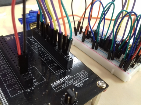
Since each peripheral supports different interfaces and protocols, you must check from the peripheral's specifications whether a specific protocol is supported. Peripheral I/O APIs are categorized based on the protocol.
Figure: Peripherals connected to an IoT device
Supported Protocols
The following table lists the supported protocols for the Tizen IoT hardware targets.
Table: Protocols supported by the Tizen IoT hardware targets
| Protocol | ARTIK 530 | Raspberry Pi 3 |
|---|---|---|
| GPIO | Yes | Yes |
| PWM | Yes | No |
| SPI | Yes | Yes |
| I2C | Yes | Yes |
| UART | Yes | Yes |
The following figures illustrate the pinout information for the Tizen IoT hardware targets.
Figure: ARTIK 530 pinout
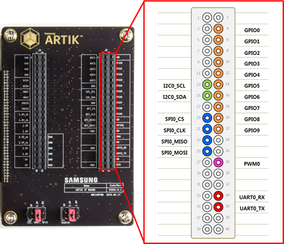
Figure: Raspberry Pi 3 pinout

Prerequisites
- To use the Peripheral I/O API, the application has to request permission by adding the following platform privilege to the
tizen-manifest.xmlfile:<privileges> <privilege>http://tizen.org/privilege/peripheralio</privilege> </privileges>
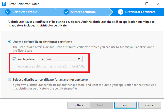
To obtain authorization to use platform-level privileges, the application must be signed with a platform-level distributor certificate. Create a certificate profile for signing the application:
- To open the Certificate Manager, in the Tizen Studio menu, go to Tools > Certificate Manager.
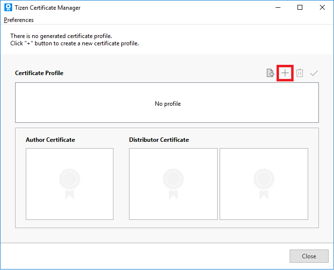
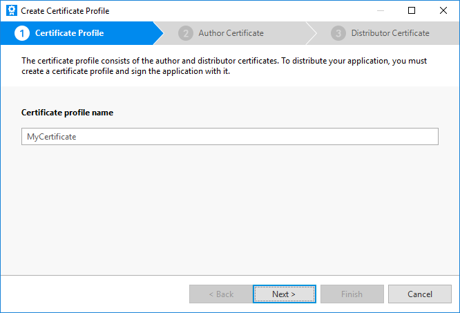
- To add a new certificate profile for signing your application, click + in the Certificate Manager and enter a profile name.
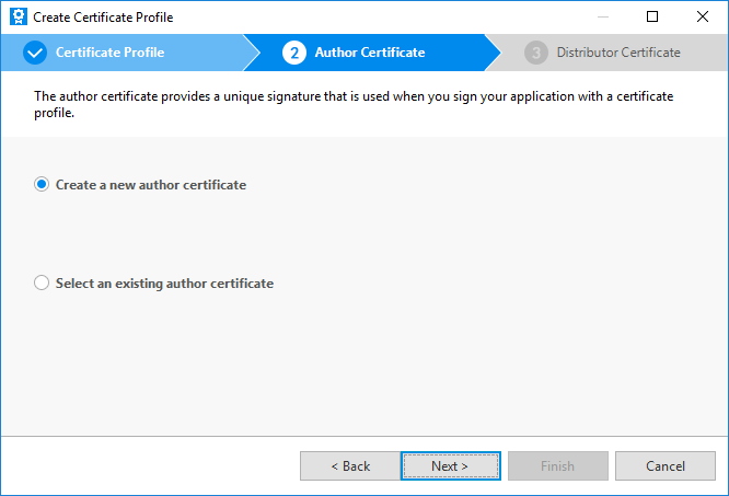
- Select Create a new author certificate and click Next.
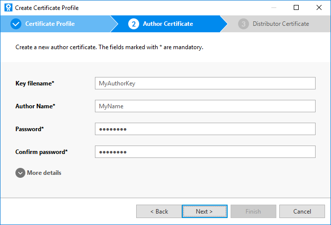
- Enter the key file name, author name, password, and password again. If you want to provide more information for the certificate, enter the details after unfolding the More details section.
- Select Use the default Tizen distributor certificate and the Platform privilege level, and click Finish.
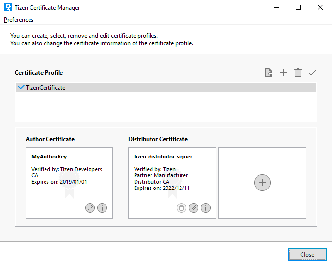
The new platform-level certificate is created and shown in the Certificate Manager.
- To open the Certificate Manager, in the Tizen Studio menu, go to Tools > Certificate Manager.
- To use the functions and data types of the Peripheral I/O API, include the
<peripheral_io.h>header file in your application:#include <peripheral_io.h>
GPIO
GPIO (General-Purpose Input/Output) is a programmable interface for reading the state of binary input peripherals, such as a switch, and controlling the state of binary output peripherals, such as a LED.
GPIO sets a direction for the data transfer. It can also detect an interrupt signaled by a level transition: either a falling edge (high to low) or a rising edge (low to high). To detect the interrupt signal you want, set the appropriate edge mode.
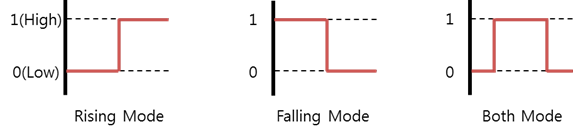
GPIO offers the following edge modes:
- Rising mode detects data changes from low to high.
- Falling mode detects data changes from high to low.
Figure: GPIO edge modes
Opening and Closing a Handle
To open and close a handle:
- To open a GPIO handle, use the
peripheral_gpio_open()function:int pin = 26; /* ARTIK 530 : GPIO8, Raspberry Pi 3 : GPIO26 */ peripheral_gpio_h gpio_h; peripheral_gpio_open(pin, &gpio_h);
The
pinparameter required for this function must be set according to the following tables.Table: ARTIK 530
Pin name Pin (parameter 1) Pin name Pin (parameter 1) GPIO0 128 GPIO1 129 GPIO2 130 GPIO3 46 GPIO4 14 GPIO5 41 GPIO6 25 GPIO7 0 GPIO8 26 GPIO9 27 Table: Raspberry Pi 3
Pin name Pin (parameter 1) Pin name Pin (parameter 1) GPIO4 4 GPIO5 5 GPIO6 6 GPIO12 12 GPIO13 13 GPIO16 16 GPIO17 17 GPIO18 18 GPIO19 19 GPIO20 20 GPIO21 21 GPIO22 22 GPIO23 23 GPIO24 24 GPIO25 25 GPIO26 26 GPIO27 27 - - NoteFor more information on the pin names and locations, see Supported Protocols. - To close a GPIO handle that is no longer used, use the
peripheral_gpio_close()function:peripheral_gpio_close(gpio_h);
Setting the Data Direction
To set the data transfer direction, use the peripheral_gpio_set_direction() function with 1 of the following direction types:
PERIPHERAL_GPIO_DIRECTION_IN: Input mode to receive data from a binary output peripheral.PERIPHERAL_GPIO_DIRECTION_OUT_INITIALLY_HIGH: Output mode to send data to a binary output peripheral. This value initializes the output peripheral state as high.PERIPHERAL_GPIO_DIRECTION_OUT_INITIALLY_LOW: Output mode to send data to a binary output peripheral. This value initializes the output peripheral state as low.
peripheral_gpio_set_direction(gpio_h, PERIPHERAL_GPIO_DIRECTION_OUT_INITIALLY_LOW);
PERIPHERAL_GPIO_DIRECTION_OUT_INITIALLY_HIGH or PERIPHERAL_GPIO_DIRECTION_OUT_INITIALLY_LOW, the edge mode must be set to PERIPHERAL_GPIO_EDGE_NONE.Setting the Edge Mode
To set the edge mode, use the peripheral_gpio_set_edge_mode() function with 1 of the following edge mode types:
PERIPHERAL_GPIO_EDGE_NONE: No edge mode.PERIPHERAL_GPIO_EDGE_RISING: Interrupted at a rising edge (low to high).PERIPHERAL_GPIO_EDGE_FALLING: Interrupted at a falling edge (high to low).PERIPHERAL_GPIO_EDGE_BOTH: Interrupted at both rising and falling edges.
peripheral_gpio_set_edge_mode(gpio_h, PERIPHERAL_GPIO_EDGE_RISING);
PERIPHERAL_GPIO_EDGE_RISING, PERIPHERAL_GPIO_EDGE_FALLING, or PERIPHERAL_GPIO_EDGE_BOTH, the data direction must be set to the PERIPHERAL_GPIO_DIRECTION_IN.Setting the Interrupted Callback
The interrupted callback is called when the GPIO state changes, based on the selected edge mode.
The interrupted callback is unset when the peripheral_gpio_unset_interrupted_cb() function is called or when the callback receives an error value other than PERIPHERAL_ERROR_NONE.
To implement the interrupted callback:
- Define the interrupted callback content.
static void
interrupted_cb(peripheral_gpio_h gpio_h, peripheral_error_e error, void *user_data)
{
    /* Code you want to run when the interrupt occurs */
}
- Set the callback with the
peripheral_gpio_set_interrupted_cb()function:peripheral_gpio_set_interrupted_cb(gpio_h, interrupted_cb, NULL);
- When no longer needed, unset the interrupt callback with the
peripheral_gpio_unset_interrupted_cb()function:peripheral_gpio_unset_interrupted_cb(gpio_h);
Reading and Writing Binary Data
To read and write binary data:
- To read binary data from a peripheral, use the
peripheral_gpio_read()function:uint32_t value; peripheral_gpio_read(gpio_h, &value);
- To write binary data to a peripheral, use the
peripheral_gpio_write()function:uint32_t value = 1; peripheral_gpio_write(gpio_h, value);
PERIPHERAL_GPIO_DIRECTION_OUT_INITIALLY_HIGHor PERIPHERAL_GPIO_DIRECTION_OUT_INITIALLY_LOW.PWM
PWM (Pulse-Width Modulation) is a programmable interface that allows you to, for example, control motor speed or change light brightness.
Peripherals that support PWM are controlled by the current strength. To modulate the current, the voltage needs to be modulated. The voltage is proportional to the intensity of the current.
To modulate the voltage, you must set the duty cycle and polarity:
- The period is a constant interval at which the pulse repeats.
- The duty cycle is the constant time within 1 period in which a signal is active.
- A "polarity high" signal starts high for the duration of the duty cycle and goes low for the remainder of the period. Conversely, a "polarity low" signal starts low for the duration of the duty cycle and goes high for the remainder of the period.
- The pulse repeats if repetition has been enabled.
Figure: Duty cycle
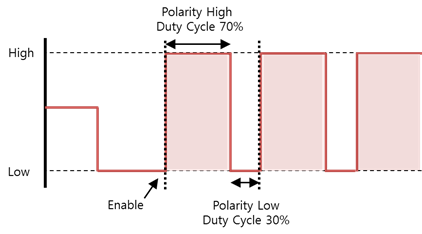
For example, if the period is 10,000,000 nanoseconds and the polarity high duty cycle is 7,000,000 nanoseconds, the average voltage is at 70%.
Figure: Average voltage per duty cycle

Opening and Closing a Handle
To open and close a handle:
- To open a PWM handle, use the
peripheral_pwm_open()function:int chip = 0; int pin = 2; peripheral_pwm_h pwm_h; peripheral_pwm_open(chip, pin, &pwm_h);
The
chipandpinparameters required for this function must be set according to the following table.Table: ARTIK 530
Pin name Chip (parameter 1) Pin (parameter 2) PWM0 0 2 NoteFor more information on the pin names and locations, see Supported Protocols. - To close a PWM handle that is no longer used, use the
peripheral_pwm_close()function:peripheral_pwm_close(pwm_h);
Setting the Period
To set the period, use the peripheral_pwm_set_period() function.
The following example sets the period to 20 milliseconds. The unit is nanoseconds.
Uint32_t period = 20000000;
peripheral_pwm_set_period(pwm_h, period);
Setting the Duty Cycle
To set the duty cycle, use the peripheral_pwm_set_duty_cycle() function.
The following example sets the duty cycle to 2 milliseconds. The unit is nanoseconds.
uint32_t duty_cycle = 2000000;
peripheral_pwm_set_duty_cycle(pwm_h, duty_cycle);
Setting the Polarity
To set the polarity, use the peripheral_gpio_set_polarity() function with 1 of the following polarity types:
PERIPHERAL_PWM_POLARITY_ACTIVE_HIGH: Polarity is high.PERIPHERAL_PWM_POLARITY_ACTIVE_LOW: Polarity is low.
peripheral_pwm_set_polarity(pwm_h, PERIPHERAL_PWM_POLARITY_ACTIVE_HIGH);
Enabling Repetition
To enable repetition, use the peripheral_pwm_set_enabled() function:
bool enable = true;
peripheral_pwm_set_enabled(pwm_h, enable);
SPI
SPI (Serial Peripheral Interface) is a programmable interface for transferring data quickly to peripherals that require high performance.
The SPI protocol is a serial communication method that controls the clock signal as master and other peripherals connected to SPI as slaves. This protocol is used by peripherals, such as heart-beat pulse sensors and graphic displays, that require fast data transfer.
Figure: SPI interface diagram
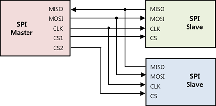
The SPI is a communication method between 1 master and multiple slave devices. In the above figure:
- CLK (SCLK or SCK) is a simple synchronization signal and a communication clock.
- The data flows from the master to the slave in the MOSI (Master Out Slave In) line, and from the slave to the master in the MISO (Master In Slave Out) line. Full duplex data communication is possible with 2 lines (MOSI and MISO).
- CS (Chip Select) is a signal for selecting a slave device.
SPI supports half duplex read/write and full duplex transfer.
To use SPI, you must set the following:
- SPI mode
Figure: SPI modes
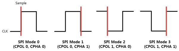
Each of the 4 available SPI modes defines a specific combination of clock polarity (CPOL) and clock phase (CPHA).
Table: SPI modes
SPI mode Polarity
(CPOL)
Phase
(CPHA)
Description SPI MODE 0 0 0 CLK (Clock) is first low and data is sampled on the rising edge of each clock pulse. SPI MODE 1 0 1 CLK is first low and data is sampled on the falling edge of each clock pulse. SPI MODE 2 1 0 CLK is first high and data is sampled on the falling edge of each clock pulse. SPI MODE 3 1 1 CLK is first high and data is sampled on the rising edge of each clock pulse. - Bit order
The bit order refers to the sequential order in which bytes are arranged into larger numerical values. MSB indicates that the most significant bit is transmitted first. LSB indicates that the least significant bit is transmitted first.
- Bit per word
The bit per word refers to the number of bits to be transmitted at a time when data is exchanged with a connected slave. Normally, it is set to 8 bits per word.
- Frequency
The frequency refers to the clock signal in Hz. Since the frequencies are different for each slave device, the applicable value must be checked from the peripheral's specification.
Opening and Closing a Handle
To open and close a handle:
- To open a SPI handle, use the
peripheral_spi_open()function:int bus = 2; int chip_select = 0; peripheral_spi_h spi_h; peripheral_spi_open(bus, chip_select, &spi_h);
The
busandchip_selectparameters required for this function must be set according to the following tables.Table: ARTIK 530
Pin name Bus (parameter 1) Chip Select (parameter 2) SPI0_MOSI SPI0_MISO SPI0_CLK SPI0_CS 2 0 Table: Raspberry Pi 3
Pin name Bus (parameter 1) Chip Select (parameter 2) SPI0_MOSI SPI0_MISO SPI0_CLK SPI0_CS0 0 0 SPI0_MOSI SPI0_MISO SPI0_CLK SPI0_CS1 0 1 NoteFor more information on the pin names and locations, see Supported Protocols. - To close a SPI handle that is no longer used, use the
peripheral_spi_close()function:peripheral_spi_close(spi_h);
Setting the SPI Mode
To set the SPI mode, use the peripheral_spi_set_mode() function with 1 of the following mode types:
PERIPHERAL_SPI_MODE_0: CLK is active high and sampled at the rising edge.PERIPHERAL_SPI_MODE_1: CLK is active high and sampled at the falling edge.PERIPHERAL_SPI_MODE_2: CLK is active low and sampled at the rising edge.PERIPHERAL_SPI_MODE_3: CLK is active low and sampled at the falling edge.
peripheral_spi_set_mode(spi_h, PERIPHERAL_SPI_MODE_1);
Setting the Bit Order
To set the bit order, use the peripheral_spi_set_bit_order() function with 1 of the following bit order types:
PERIPHERAL_SPI_BIT_ORDER_MSB: Use the most significant bit first.PERIPHERAL_SPI_BIT_ORDER_LSB: Use the least significant bit first.
peripheral_spi_set_bit_order(spi_h, PERIPHERAL_SPI_BIT_ORDER_MSB);
Setting the Bits per Word
To set the bits per word, use the peripheral_spi_set_bits_per_word() function:
uint8_t bits_per_word = 8;
peripheral_spi_set_bits_per_word(spi_h, bits_per_word);
Setting the Frequency
To set the frequency, use the peripheral_spi_set_frequency() function.
The frequency unit is Hz.
uint32_t frequency = 1024;
peripheral_spi_set_frequency(spi_h, frequency);
Reading, Writing, and Transferring Data
To read, write, and transfer data:
- To read data from a slave device, use the
peripheral_spi_read()function:uint8_t data; uint32_t length = 1; peripheral_spi_read(spi_h, &data, length);
- To write data to a slave device, use the
peripheral_spi_write()function:uint8_t data = 0x80; uint32_t length = 1; peripheral_spi_read(spi_h, &data, length);
- To exchange bytes data with a slave device, use the
peripheral_spi_transfer()function:uint8_t tx_data[2] = {0x80, 0x01}; uint8_t rx_data[2]; uint32_t length = 2; peripheral_spi_transfer(spi_h, tx_data, rx_data, length);
I²C
I2C (Inter-Integrated Circuit) is a programmable interface that allows you to communicate with I2C peripherals.
I2C is a synchronous serial interface that uses a clock signal to synchronize data transfers between master and slave device:
- Master device generates the clock and initiates communication with slaves.
- Slave device receives the clock and responds when addressed by the master.
Figure: I2C interface diagram
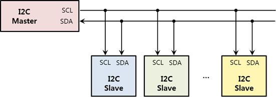
To allow the I2C master to connect to 128 I2C slave devices, an I2C slave device provides a 7-bit address. Since most slave addresses are determined by the manufacturer, refer to the specification to find the slave device address.
Using the I2C bus, the master controls signal lines called SCL (Shared CLock) and SDA (Shared DAta) to read or write data to or from the device. SCL is a clock line for communication synchronization, and SDA is a data line. The master outputs the clock for synchronization with the SCL, and the slave outputs or receives data through the SDA according to the clock output to the SCL.
If the SDA line is used alone, only half duplex communication is possible because data is sent only to 1 line.
Opening and Closing a Handle
To open and close a handle:
- To open an I2C handle, use the
peripheral_i2c_open()function:int bus = 1; int address = ...; /* See the specification */ peripheral_i2c_h i2c_h; peripheral_i2c_open(bus, address, &i2c_h);
The
busparameter required for this function must be set according to the following table.Table: ARTIK 530 / Raspberry Pi 3
Pin name Bus number (parameter 1) I2C1_SDA I2C1_SCL 1 NoteFor more information on the pin names and locations, see Supported Protocols.The
addressparameter must be set based on the peripheral specification.
- To close an I2C handle that is no longer used, use the
peripheral_i2c_close()function:peripheral_i2c_close(i2c_h);
Reading and Writing Data
To read and write data:
- To write bytes to a slave device, use the
peripheral_i2c_write()function:uint8_t data[2] = {0x06, 0x01}; uint32_t length = 2; peripheral_i2c_write(i2c_h, data, length);
- To read bytes from a slave device, use the
peripheral_i2c_read()function:uint8_t data[2]; uint32_t length = 2; peripheral_i2c_read(i2c_h, data, length);
Reading and Writing Register Data
To read and write register data:
- To write single byte data to a slave device register, use the
peripheral_i2c_write_register_byte()function:uint8_t data = 0x06; uint8_t register_address = ...; /* See the specification */ peripheral_i2c_write_register_byte(i2c_h, register_address, data);
- To read single byte data from a slave device register, use the
peripheral_i2c_read_register_byte()function:uint8_t data ; uint8_t register_address = ...; /* See the specification */ peripheral_i2c_read_register_byte(i2c_h, register_address, &data);
- To write word data to a slave device register, use the
peripheral_i2c_write_register_word()function:uint16_t data = 0xffff; uint8_t register_address = ...; /* See the specification */ peripheral_i2c_write_register_word(i2c_h, register_address, data);
- To read word data from a slave device register, use the
peripheral_i2c_read_register_word()function:uint16_t data ; uint8_t register_address = ...; /* See the specification */ peripheral_i2c_read_register_word(i2c_h, register_address, &data);
UART
UART (Universal Asynchronous Receiver-Transmitter) is a programmable interface that allows you to communicate 1:1 with a UART peripheral.
Figure: UART interface diagram

UART is an interface for exchanging data with peripherals. It is an asynchronous method that transmits data without a clock line, and consists of only 2 data lines: transmit (Tx) and receive (Rx). UART performs 1:1 communication.
Figure: UART data frame
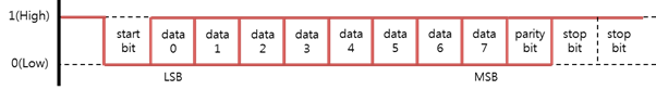
The UART data frame consists of start (1 bit), data (5~8 bit), parity (1 bit) and stop (1 bit):
- Start bit
Indicates the start of the communication before sending data and holds it for a bit time length.
- Data
Transmits 5 to 8 bits of data.
- Parity bit
Generates and transmits a parity value for error verification, and determines a receiving side error. The following options are available:
None,Even, andOddparity. SelectingNoneremoves this bit. - Stop bit
Indicates the termination of the communication and holds 1 or 2 bits.
- Baud rate
Asynchronous transmission/receiving speeds must be matched to the peripheral. For this purpose, the number of signals transmitted per second can be synchronized with a peripheral. It is called the Baud.
If a device supports a 5-wire UART port, hardware flow control can be used to increase the reliability of the data transmission. Software flow control can also be used to increase reliability.
Opening and Closing a Handle
To open and close a handle:
- To open a UART handle, use the
peripheral_uart_open()function:int port = 4; /* ARTIK 530 : UART0 */ peripheral_uart_h uart_h; peripheral_uart_open(port, &uart_h);
The
portparameter required for this function must be set according to the following tables.Table: ARTIK 530
Pin name Port (parameter 1) UART0_RX UART0_TX 4 Table: Raspberry Pi 3
Pin name Port (parameter 1) UART0_RX UART0_TX 0 NoteFor more information on the pin names and locations, see Supported Protocols. - To close a UART handle that is no longer used, use the
peripheral_uart_close()function:peripheral_uart_close(uart_h);
Setting the Baud Rate
To set the baud rate, use the peripheral_uart_set_baud_rate() function with a baud rate value:
PERIPHERAL_UART_BAUD_RATE_0~PERIPHERAL_UART_BAUD_RATE_230400
peripheral_uart_set_baud_rate(uart_h, PERIPHERAL_UART_BAUD_RATE_9600);
Setting the Byte Size
To set the byte size, use the peripheral_uart_set_byte_size() function with 1 of the following byte size types:
PERIPHERAL_UART_BYTE_SIZE_5BIT: Byte size is 5 bits.PERIPHERAL_UART_BYTE_SIZE_6BIT: Byte size is 6 bits.PERIPHERAL_UART_BYTE_SIZE_7BIT: Byte size is 7 bits.PERIPHERAL_UART_BYTE_SIZE_8BIT: Byte size is 8 bits.
peripheral_uart_set_byte_size(uart_h, PERIPHERAL_UART_BYTE_SIZE_7);
Setting the Parity Bit
To set the parity bit, use the peripheral_uart_set_parity() function with 1 of the following parity types:
PERIPHERAL_UART_PARITY_NONE: No parity bit.PERIPHERAL_UART_PARITY_EVEN: Parity bit is even.PERIPHERAL_UART_PARITY_ODD: Parity bit is odd.
peripheral_uart_set_parity(uart_h, PERIPHERAL_UART_PARITY_EVEN);
Setting the Stop Bits
To set the stop bits, use the peripheral_uart_set_stop_bits() function with 1 of the following stop bit types:
PERIPHERAL_UART_STOP_BITS_1BIT: 1 bit is used for stop bits.PERIPHERAL_UART_STOP_BITS_2BIT: 2 bit is used for stop bits.
peripheral_uart_set_stop_bits(uart_h, PERIPHERAL_UART_STOP_BITS_2BIT);
Setting the Flow Control
To set the hardware and software flow control, use the peripheral_uart_set_flow_control() function with 1 of the following flow control types:
PERIPHERAL_UART_SOFTWARE_FLOW_CONTROL_NONE: No software flow control.PERIPHERAL_UART_SOFTWARE_FLOW_CONTROL_XONXOFF: Software flow control uses XONXOFF.PERIPHERAL_UART_HARDWARE_FLOW_CONTROL_NONE: No hardware flow control.PERIPHERAL_UART_HARDWARE_FLOW_CONTROL_AUTO_RTSCTS: Hardware flow control uses RTSCTS.
peripheral_uart_set_flow_control(uart_h, PERIPHERAL_UART_SOFTWARE_FLOW_CONTROL_XONXOFF, PERIPHERAL_UART_HARDWARE_FLOW_CONTROL_AUTO_RTSCTS);
Reading and Writing Data
To read and write data:
- To write data to a slave device, use the
peripheral_uart_write()function:uint8_t data[2] = {0x06, 0x01}; uint32_t length = 2; peripheral_uart_write(uart_h, data, length);
- To read data from a slave device, use the
peripheral_uart_read()function:uint8_t data[2]; uint32_t length = 2; peripheral_uart_read(uart_h, data, length);
'IT > Tizen' 카테고리의 다른 글
| [Tizen] System Information 변경하기 (0) | 2019.07.29 |
|---|---|
| [2019 서울 하드웨어 해커톤] '사람들의 간절한 문제를 해결하는 탑 메이커'를 주제로한 서울 하드웨어 해커톤 | Seoul Hardware Hackathon, Top Maker (0) | 2019.07.24 |
| [2019 타이젠 워크숍] 리눅스기반 고성능 하드웨어 플랫폼 타이젠 (0) | 2019.07.23 |
| 서울시-SBA 메이커스랩 G·CAMP, 사물인터넷용 리눅스 보드 출시 (0) | 2019.07.22 |
| [워크숍] 서울시 IoT 센터 - 타이젠 기반 IoT 개발 (0) | 2018.08.07 |
| Tizen Studio 2.0 설치경로에 빈칸이 있으면, Remote Device Manager에서 디바이스가 안붙는 문제 (2) | 2017.12.07 |
| Tizen Studio 1.3 → 2.0 업그레이드 후 Connection Explorer View가 깨지는 문제 (0) | 2017.11.28 |
| Tizen Studio 2.0 "Decoration Calculation" 에러 해결하기 (0) | 2017.11.27 |
| NIPA x Tizen Talks "타이젠을 활용하여 IoT 쉽게 만들기"('17. 11. 30) (0) | 2017.11.24 |
| Devlab x Tizen Talks "타이젠을 활용하여 IoT 쉽게 만들기"('17. 11. 21) (0) | 2017.11.15 |


